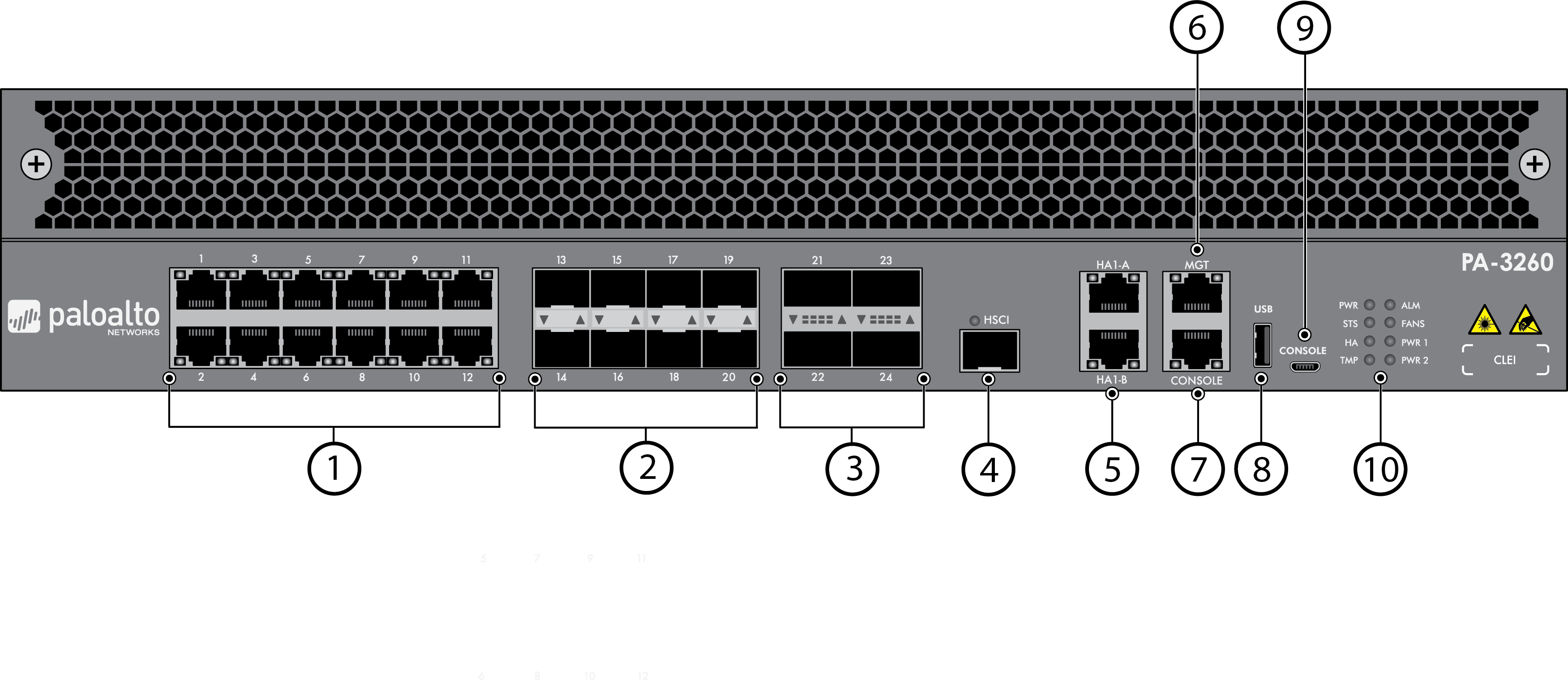
Overview:
The Palo Alto Networks® PA-3200 Series next-generation firewalls are designed for data center and internet gateway deployments. This series is comprised of the PA-3250, PA-3250, and PA-3260 firewalls. These models provide flexibility in performance and redundancy to help you meet your deployment requirements. All models in this series provide next-generation security features to help you secure your organization through advanced visibility and control of applications, users, and content.
First Supported Software Release: PAN-OS® 8.1
Features:
- 6.3 Gbps firewall throughput
(App-ID enabled1)
- 3 Gbps Threat Prevention throughput2
- 3.2 Gbps IPsec VPN throughput
- 2,000,000 sessions
- 94,000 new sessions per second3
- 6,000 IPsec VPN tunnels/tunnel interfaces
- 2,048 SSL VPN Users
- 10 virtual routers
- 1/6 virtual systems (base/max4)
- 60 security zones
- 5,000 max number of policies
Front Panel:

Item |
Component |
Description |
1 |
Ethernet ports 1 through 12 |
Twelve RJ-45 10Mbps/100Mpbs/1Gbps ports
for network traffic. The link speed and link duplex are auto-negotiate
only. |
2 |
SFP ports 13 through 20 |
These ports vary depending on your firewall model:
- PA-3250 firewall—Ports 13 through 16 are SFP (1Gbps)
and ports 17 through 20 are SFP or SFP+ (10Gbps) based on the installed
transceiver.
- PA-3250 and PA-3260 firewalls—Ports 13 through 20 are
SFP (1Gbps) or SFP+ (10Gbps) based on the installed transceiver.
|
3 |
QSFP+ ports 21 through 24 |
(PA-3260 only) Four QSFP+ (40Gbps)
ports as defined by the IEEE 802.3ba standard. |
4 |
HSCI port |
One SFP+ (10Gbps) port (supports only an
SFP+ transceiver or passive SFP+ cable).
Use this port to
connect two PA-3200 Series firewalls in a high availability (HA)
configuration as follows:
The
HSCI ports must be connected directly between the two firewalls
in the HA configuration (without a switch or router between them).
When directly connecting the HSCI ports between two PA-3200 Series
firewalls that are physically located near each other, Palo Alto
Networks recommends that you use a passive SFP+ cable.
For
installations where the two firewalls are not near each other and
you cannot use a passive SFP+ cable, use a standard SFP+ transceiver
and the appropriate cable length.
|
5 |
HA1-A and HA1-B ports |
Two RJ-45 10Mbps/100Mbps/1000Mbps ports
for high availability (HA) control.
If the firewall
dataplane restarts due to a failure or manual restart, the HA1-B
link will also restart. If the dataplane restarts and only HA1-B
is connected, a split brain condition occurs. The HA1-A link will
not restart when the dataplane restarts. Because of this behavior,
we recommend that you connect both HA1-A and HA1-B to provide redundancy
for the control link and to avoid split brain issues.
|
6 |
MGT port |
Use this Ethernet 10Mbps/100Mbps/1000Mbps port
to access the management web interface and perform administrative
tasks. The firewall also uses this port for management services,
such as retrieving licenses and updating threat and application
signatures. |
| 7 |
CONSOLE port (RJ-45) |
Use this port to connect a management computer to
the firewall using a 9-pin serial-to-RJ-45 cable and terminal emulation
software.
The console connection provides access to firewall boot
messages, the Maintenance Recovery Tool (MRT), and the command line
interface (CLI).
If your management computer does
not have a serial port, use a USB-to-serial converter.
Use
the following settings to configure your terminal emulation software
to connect to the console port:
- Data rate: 9600
-
Data bits: 8
-
Parity: None
-
Stop bits: 1
-
Flow control: None
|
| 8 |
USB port |
A USB port that accepts a USB flash drive
with a bootstrap bundle (PAN-OS configuration).
Bootstrapping
speeds up the process of configuring and licensing the firewall
to make it operational on the network with or without internet access. |
| 9 |
CONSOLE port (Micro USB) |
Use this port to connect a management computer to
the firewall using a standard Type-A USB-to-micro USB cable.
The
console connection provides access to firewall boot messages, the
Maintenance Recovery Tool (MRT), and the command line interface
(CLI).
Refer to the Micro USB Console Port page for more information
and to download the Windows driver or to learn how to connect from
a Mac or Linux computer. |
10 |
LED status indicators |
|
Back Panel:

Item |
Component |
Description |
1 |
System drive |
One 240GB solid-state drive (SSD) used to
store the PAN-OS system files, system logs, and network traffic
logs. |
2 |
Exhaust fan tray |
Provides ventilation and cooling for the firewall. |
3 |
Ground studs |
Use the two-post ground stud to connect the
firewall to earth ground. The firewall ships with a 6AWG two-post
ground lug (attached to the ground studs) but does not include a
ground cable. |
| 4 |
PS1 and PS2
power supplies |
Use the power supply inputs (either AC or DC
depending on the installed power supply type) to connect power to
the firewall. The second power supply is for redundancy. When facing
the back of the firewall, PS1 is on the left and PS2 is on the right. |


